8NN Helmer mockup
Table of Contents
Exploring the idea that a minimal, on-the-cheap autohelm capable of maintaining a specified bearing can be built from a microcontroller reading a cheap guidance sensor (GPS position over time, magnetic compass heading and possibly intertial corrections) driving existing electric trim tabs on my 21' Trophy diesel I/O powerboat.
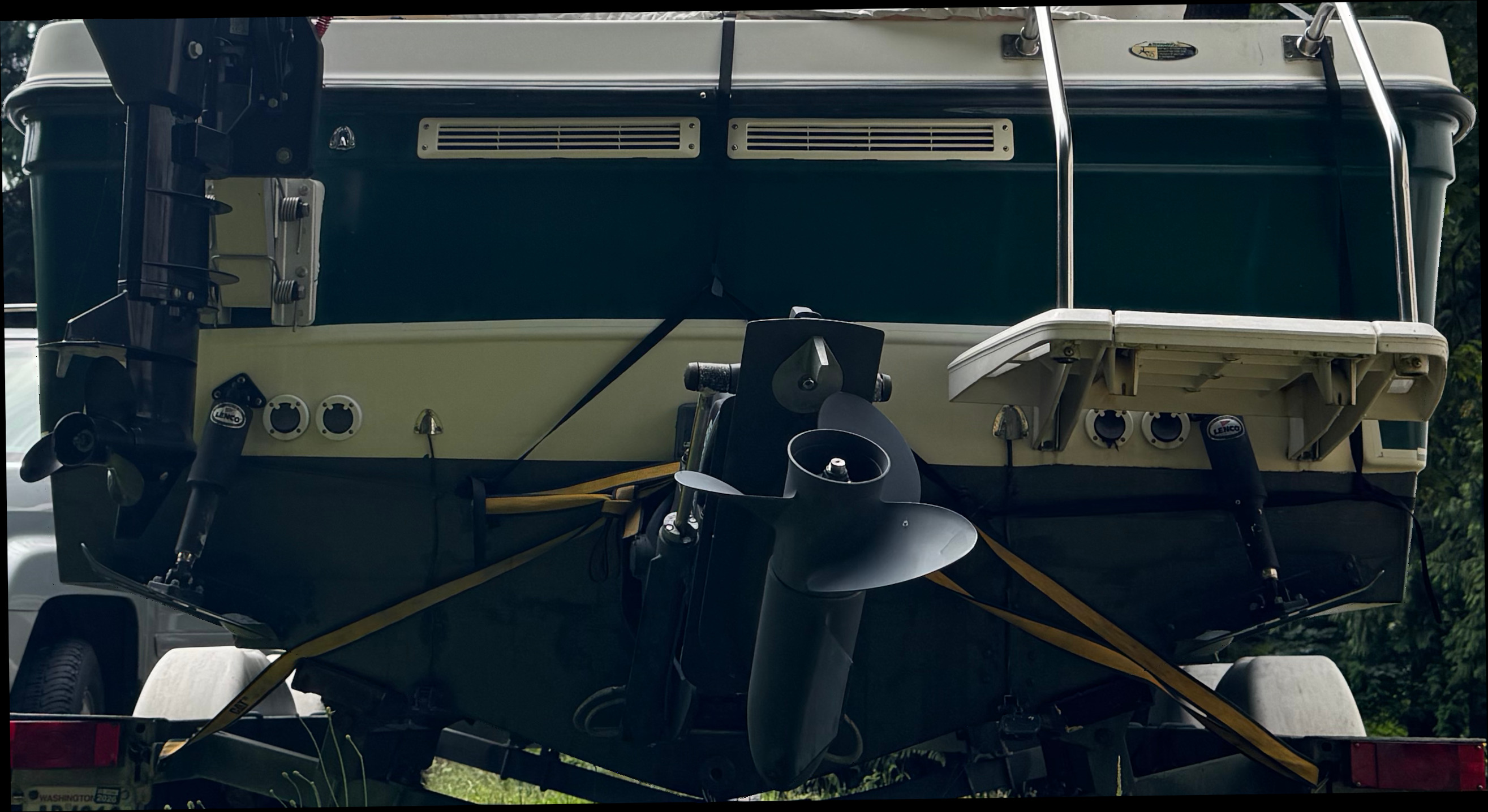
A stern view of 8NN trailered, showing outdrive in the up position and trim tabs near neutral.
Introductory overview
With this document I am exploring the idea that a minimal, on-the-cheap autohelm capable of maintaining a specified bearing can be built from a microcontroller reading a cheap guidance sensor (GPS position over time, magnetic compass heading and possibly intertial corrections) driving existing electric trim tabs on my 21' Trophy diesel inboard/outboard (I/O) powerboat.
By "maintaining a specified bearing" I mean that, if the autohelm is engaged while the boat is moving in a steady direction and speed, the autohelm will keep it moving in that direction. "Bearing" is distinct from "heading", in that "maintaing a heading" would mean keeping the bow pointed in the same direction. Current and wind effects account for the difference; heading is maintained with respect to a compass while bearing is maintained with respect to a sequence of GPS coordinates.
The boat
My 8NN is a Trophy 2052WA built by Brunswick Family Boats as a 2004 model, a fiberglass cuddy-cabin hardtop sportfisher with a moderate V hull. Powertrain is Mercury Marine's 120HP turbodiesel spinning a Mercruiser Alpha One (Gen2) outdrive, which is a housing attached by gimbals to the transom (stern, or back), carrying shafts and gears and a forward/reverse shift mechanism that transmits engine output motion to the propellor screw in the water below the level of the hull.
Steering is by an unassisted push-pull cable swinging the entire outdrive side to side, so the direction of thrust of the prop changes and the portion of the outdrive housing below the level of the hull acts as a rudder. It is driven by a rack-and-pinion mechanism at the helm wheel end, and features (is marred by) a considerable deadband caused mostly by clearance between the cable and its housing as it transits a complex path from helm to outdrive. This deadband amounts to about four inches of free travel at the wheel's rim.
Outdrive (bow up/down) trim
I/O drives can be raised and lowered, pivoting near the waterline, by a hydraulic/electric ram system. On 8NN this system is controlled by a switch on the power lever. Trailering or beaching the boat requires raising the drive unit clear of the bottom of the hull, pivoting the propellor's axle shaft about 60 degrees from horizontal (with respect to hull viewed from the side with the helm straight). Smaller running changes near the horizontal position optimize speed over the water and wave pounding depending on power setting, fore-and-aft weight balance and wind and wave conditions.
Balance (side to side) trim
A small metal surface (a bit less than one square foot) is hinged to the bottom of the transom on each side, coplanar in the neutral position with the planing surface on that side but adjustable in angle by electric actuators to around ten degrees up or down. On 8NN these trim tabs are controlled by two two-position momentary contact switches to the right of the helm (awkwardly mounted facing port, not aft, making their effects hard to deduce).
Each switch applies power via a voltage in one polarity or the other to a linear actuator on one trim tab, moving that tab up or down within its range of motion by an amount that can (presumably) be modeled by a function of the amount of time the switch is closed, the amount of time since the switch was last opened, and the polarity of the previous switch motion. The time required to transit the range of motion is about four seconds. Note that at higher speeds the tab can be out of contact with the water surface in its higher positions, reducing the effective travel of the tab upward.
There is no feedback mechanism to determine current tab position. The tab can only be run to one end of its travel by power in that direction for the full-range travel time, and its position modeled by a function as described above. Errors will accumulate, so some heuristic will be needed to effect a periodic reset of the modeling function's state.
- Boat response to trim tabs…
Moved together in the same direction the trim tabs have a similar effect on bow up/down trim as the outdrive trim control, changing the angle of the planing surfaces and in turn affecting boat speed and wave pounding. These effects can be dramatic, as the boat can fall off plane when the bow is held too high or the prop can ventilate if the outdrive is held too high. They can also be subtle, as relatively small changes in bow-up trim (and in how the same amount of bow-up trim is effected by tabs and by outdrive position) can change boat speed measureably but over a long period (seconds to minutes).
Moved opposite one another the trim tabs can counteract side-to-side weight and side wind balance forces to keep the boat level when running straight ahead, or deliberately tilted to one side or the other to reduce pounding from quartering waves in some sea conditions. Changing the position of a tab changes water drag on that side, usually requiring a significant change in helm position to maintain a course.
Spoiler alert: We're going to be talking about the opposite effect, using this change in drag to maintain a course without changing helm position.
- …is complicated.
Note that simply tilting the boat, whether with differential trim tab position changes or by moving mass from one side of the boat to the other, can change its turning moment. It can be complicated, with several effects more or less cancelling each other out but this balance varying with speed and the boat's weight and weight balance.
In transverse cross-section this boat's hull surfaces come together in a V shape at an angle that changes from quite steep nearer the bow (30 degrees and more from horizontal ahead of where the bow curve ends in elevation, from the side, about halfway back) to its value at the transom, which is called "deadrise" and which measures 14 degrees on 8NN. All of these tilted surfaces push water both down and to the side, putting force on the boat hull at that point with a yaw component toward the other side (and a lift component upward and a drag component rearward, not of interest just now). Running straight ahead in still water the sideways forces from each side balance, so absent other turning moments the boat continues straight. But tilt the boat, say by transferring some of its weight toward one side, and the suface on the higher side become closer to vertical at each section, so its yaw component becomes higher in proportion to lift and drag. Correspondingly the lower side, more horizontal, loses some of its yaw component to lift and drag. The yaw balance changes, introducing a yaw moment in the direction of the lower side.
At the same time, the lower side has more surface immersed in water while the higher side puts more of its surface in free air. This difference in parasite drag also causes a yaw moment in the direction of the lower side, but because the total force exerted by the higher side is less (with less surface in the water there's less drag but also less effect of the water dynamically pushing on the surface) the yaw component it offers favoring a turn to the low side goes down in total, even as it goes up in proportion to lift and drag components, favoring a turn to the high side.
IRL the combined effect of all these second-order effects of tilting the boat from side to side can vary, particularly with boat speed and fore/aft mass balance. 8NN can carry 600lbs of fuel sloshing around in a long flat tank near the keel, so mass balance is always changing. Again, and in summary, it (boat response to differential trim tab position changes) is complicated.
Steering trim
Propellor forces at any forward power setting tend to push the outdrive into a turn to port. An angle-adjustable vertical trim tab in the prop wash is set to counteract this force, pushing the outdrive to starboard. The prop and trim tab force balance changes with boat speed and outdrive trim, so the tab angle gets set by trial and error to a reasonable compromise position. The tab doubles as a sacrificial anode, so its ideal position changes as it erodes over time.
The problem
Like most short and wide planing-hull boats, at low speeds (off plane) the helm is unstable. Holding the wheel in a straight-ahead position the boat will maintain a heading for only a few seconds before falling off to one side or the other. This heading change speeds up or slows down and even reverses but unpredictably. If left uncorrected the boat follows a random sinuous course that has nothing to do with the pilot's intention, or with the position of obstacles nearby. The pilot's corrective helm motions tend to overshoot and lead to a more stable oscillation that averages out to the intended course but requires moment-to-moment attention. If the wheel is left untended the initial turn puts steering force on the outdrive that pushes it into the turn, leading to bhe boat going in a stable circle with the helm at full lock one way or the other.
At higher speeds, cruising on plane, the helm is generally stable but ever-changing wind and water forces and side-to-side balance changes (as passengers move, for example) work to push any boat off course. Play in the steering plus usually unbalanced steering trim raise the pilot's workload here too. Even if the tab and prop forces are balanced the helm can't be left untended for more than a few seconds without a change in heading changing the balance of forces and usually leading to a slow turn of slowly decreasing radius.
In both cases fast and slow the pilot's eyes must be on the horizon and hands on the wheel most of the time, attention focused on maintaining course. This isn't a terrible thing, especially here in Salish Sea waters where floating logs and other detritus are common and vessel traffic can be heavy and fast. The pilot needs to be focused on the water ahead, navigating and looking for obstacles and maneuvering to avoid them. But operating a boat involves more tasks than simply steering, particularly at the start and end of a journey, and steering by itself is wearying when corrections are relentless hour after hour.
Solutions exist
The answer to this problem already exists in a myriad of automatic helm monitors, if you're willing to afford one. For powerboats most or all are electronic, incorporating a machine-readable magnetic or gyroscopic or inertial compass and a mechanical steering actuator, with a computer mediating between them. They work great and they're widely available.
For me though this problem is a hobby-level annoyance, certainly not something worth buying and installing thousands' worth of equipment to fix. And I do mean thousands: I don't find electric linear actuators specific to the Alpha One outdrive, and simple chain-drive electric rotary actuators capable of enough force to steer this boat are at least $2k for the actuator by itself. And the aesthetics of installations like this are awful.
Hydraulic linear actuators are available, costing even more with their pump (still before considering the control head). And 8NN doesn't have hydraulic steering, a nice retrofit but yet another several thousand dollars in additional costs along with the risk that the power steering pump through its belt siphons off the very last bit of power sometimes required to keep this boat on plane without melting a piston. (Which is not necessarily hyperbole, as this is a high-speed turbodiesel with mechanical controls and none of the guidance given by other vendors of similar powerplants regarding maximum continuous power settings, but anecdotal evidence exists suggesting that exceeding 90% of max RPMs indefinitely is not a good idea).
The solution discussed here
My conjectural solution uses the drag changes caused by differential trim tab movements to induce small yaw forces that I hope will be enough to maintain a course in most steady conditions. I'll drive the actuators via FETs switched by a microcontroller, with GPS and a multi-DOF integrated navigation sensor (integrating a magnetic compass and three-axis intertia sensors) providing bearing and heading information. The central control loop is probably a PID model as described on Wikipedia, with measured bearing as PV, intended bearing as SP and some function mapping the control value to activations of the trim tab actuators.
- Switching the actuators safely
Working backward from the end of the chain, finding a way to switch the actuators that doesn't compromise the existing trim tab controls is an absolute requirement. A 4PDT relay that is energized when the autohelm is active can isolate those switches from the actuators, leaving their existing current paths intact when autohelm is off.
When isolated the switches' contacts can be associated with the autohelm through the NO side of this relay, providing a control mechanism (maybe a 10-degree or 1-degree course change one way or the other for each debounced trailing edge).
Current through the actuators by the microcontroller can be via FETs, incorporating a NAND gate driving one FET to make power available only when an "up" or "down" command establishes polarity in one direction or the other. The goal with the NAND gate is to reduce the possibility that a software or microcontroller hardware error allows a short circuit that would disable the trim tab system altogether - by blowing its circuit breaker or worse, burning up a wire (and maybe something else with it).
- Driving the actuators to intended positions
Controller theory suggests considering this system in terms of a setpoint SP representing the intended bearing, an present value PV representing the current bearing (and, along with it, some past states of the bearing, or of the bearing error correction required), and a control value that the controller varies to converge the PV onto the SP. The control value here represents the amount of difference between the up/down positions of the two trim tabs, but as noted above these positions aren't directly knowable.
- Modeling tab position…
Instead the controller could maintain a model of each actuator's state as a cumulative function of up/down switch actions. The linear actuators appear to involve rotary components with substantial inertia, so the model would have to account for the time motors spend spinning up once powered up and spinning down when deenergized, and for the additional spinup time required when still spinning down from a previous actuation (in either direction, with different effects).
- …accounting for dynamic loads…
It seems likely the actuator's speed of movement under the load of dynamic water pressure on the underside of the trim tab will be different than when it is unloaded, and in consequence that the speed changes over the range of movement as down-most positions will exert more pressure upward against the actuator than upper positions.
- …and accounting for temperature and electric power supply variations…
It also seems likely the actuators' speeds depend on the voltage available to them at the moment they are activated, which might vary at different engine speeds and battery states of charge and with other unrelated electric draws on the boat's power bus. It might be necessary to monitor voltage and current through the actuators to make the model sufficiently accurate.
The acutators' speeds might also vary with temperature, I don't know. Temperature sensors could be associated with each actuator to account for this. Yuck.
- …and finding initial position…
At system startup the tabs might be in any position, so initializing the model might require setting a zero point by driving the tabs to the end of their travel one way or the other for a time exceeding the known time for a full sweep under any conditions of load in that direction.
Safety suggests the zero position should be "up", as some boats are prone to broaching or pitchpoling if trimmed too far nose-down in some conditions. Mine is not; the smaller but more likely insistent problem is of the boat falling off plane when operated at efficient cruising power settings when the bow is raised. Even so it might be wise to train the operator to increase power before activating the autohelm and adjust it back down a few seconds later, once the autohelm cycles the trim tabs.
- …and managing accumulated errors…
Errors in the position models would accumulate over time. Eventually the control algorithm will run one tab or the other to the end of its travel while it is still modeled within its operating range, or believe the tab has reached the end of its travel when in fact travel remains. Some way of coping with this situation might be necessary.
- …while maintaing some amount of trim ability in both pitch and roll.
Lest we forget, the reason the trim tabs are on the boat in the first place is to keep it trimmed in roll and to help the outdrive keep it trimmed in pitch. It might be nice if pitch trim management, to optimize boat speed at the current power setting, can be automated (probably with pilot input available, likely in the form of simultaneous presses of the existing trim-control switches).
This might involve another separate control loop also providing adjustments to the trim tab positions, but always in the same direction and in the same amount. By contrast the autohelm adjustments are always differential. I can notice some interplay between steering and pitch trim, but the autohelm adjustments will need to be relatively fast to be useful. By contrast a useful pitch management control loop will need to run slowly, as pitch adjustments affect boat speed only with a significant lag (and in different directions under different conditions, but that's another topic). In fact the boat's pitch itself can only be known by averaging widely varying pitch observations over time, but it seems likely that automating pitch trim won't involve measuring pitch at all, just the effect of trim on boat speed. It might be that the two control operations interfere with each other minimally - or even beneficially, as noted below.
I'll hold off investigating pitch management for now, since an intermediate step in the full implementation would be to hand pitch management back to the pilot (re-upping the pilot's workload, and so serving as incentive to do this additional work of automating the task).
We're kind of giving up the roll control in favor of controlling yaw with the trim tabs instead, but notice the pilot can roll the boat manually by moving the wheel. A small steering input that turns the boat to port will roll the boat to port as well. The autohelm's adjustments to the bearing change that results will initially roll the boat back to starboard, maybe more or maybe less than the wheel input rolled it to port, but those adjustments will be reversed out as the boat returns to the SP course. The steering roll will tend to remain.
- Or maybe not modeling trim tab positions at all
Maybe it won't be necessary to correct accumulated position modeling error. The operant control value (for bearing/yaw management) isn't the absolute position of either trim tab, it's their differential position. Adjustments to this differential position are in each cycle "more" or "less" - the actual value of the differential isn't important. At every point after an adjustment is made the modeling of this differential position value might as well be reset to zero (with the same adjustment made to stored past values in the controller's PID model).
Similarly a pitch management system trying to optimize boat speed doesn't necessarily care about the absolute position of the tabs, only that they might need to be a little down or a little up from where they are now, and to remember where they have been for a few cycles in case that helps the algorithm.
Also, extending the scope of the project to include automatic pitch-trim management might help the accumulating error problem. At some point accumulated position modeling error will run a trim tab against one end or the other of its range of travel, unbeknownst to the model (since there's no feedback mechanism - no position sensors on the tabs or actuators). If both tabs are at opposite ends of their range of travel, then we're up against the physical limit of the trim tabs to keep the boat running straight - the autohelm is outside its region of authority, likely with dire enough results in terms of boat attitude that the pilot is already getting involved. Otherwise the autohelm can continue to order differential tab movements and they will have effect, but with only one tab actually moving so the effect is likely smaller. A pitch management loop that "hunts" the common tab position up or down seeking improvements in boat speed will serve to bring the tabs' actual positions closer together (as well as unwinding the probably bad boat performance that results from tabs being near opposite extremes, presumably from correcting the effect of a transient yaw force or of a significant SP change).
The system already possesses an all-axis position and acceleration sensor, a GPS that knows its speed over the ground, and sometimes-functioning pitot and paddlewheel speed-over-water sensors. It might be possible to slowly modulate overall pitch (by making small adjustments to both trim tabs in the same direction) to maximize boat speed. This wouldn't be easy, and might be flakey in that better speed in current conditions is a very noisy signal to watch.
- Modeling tab position…